- This is a simple KeyPad Made by Push Buttons , can be extended to any functionalities.
- These buttons can be placed in different places in robotic applications.
- This design does not need any library and also can be expandable to more buttons.
- This design Does not need any Resistors and also does not use any libraries
Parts Required:
- 16 Push Button Switches
- Arduino uno
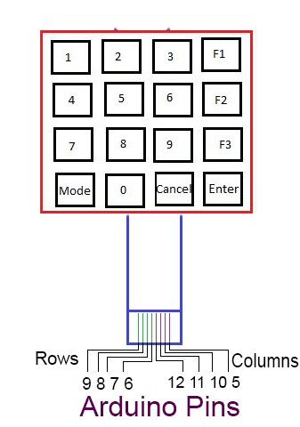
Connection
- Row Pin Row0 -> Pin 9 of Arduino
- Row Pin Row1 -> Pin 8 of Arduino
- Row Pin Row2 -> Pin 7 of Arduino
- Row Pin Row2 -> Pin 6 of Arduino
- Col Pin Col0 -> Pin 12 of Arduino
- Col Pin Col1 -> Pin 11 of Arduino
- Col Pin Col2 -> Pin 10 of Arduino
- Col Pin Col3 -> Pin 5 of Arduino
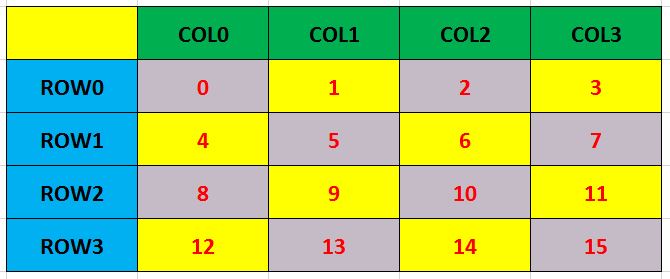
Trick is to Use
Find index of any pressed button and assign it
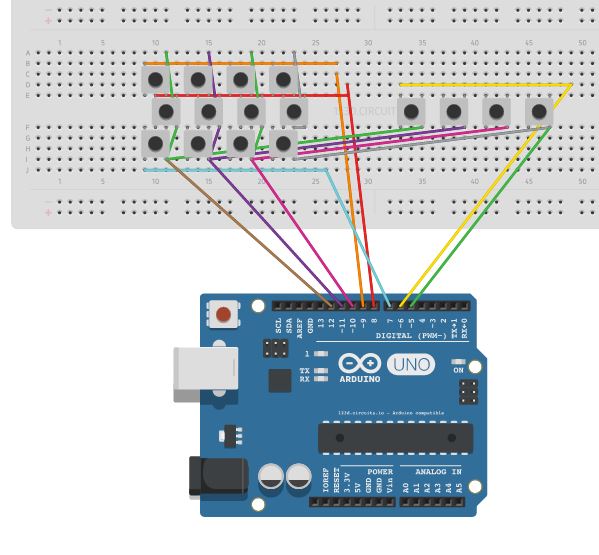
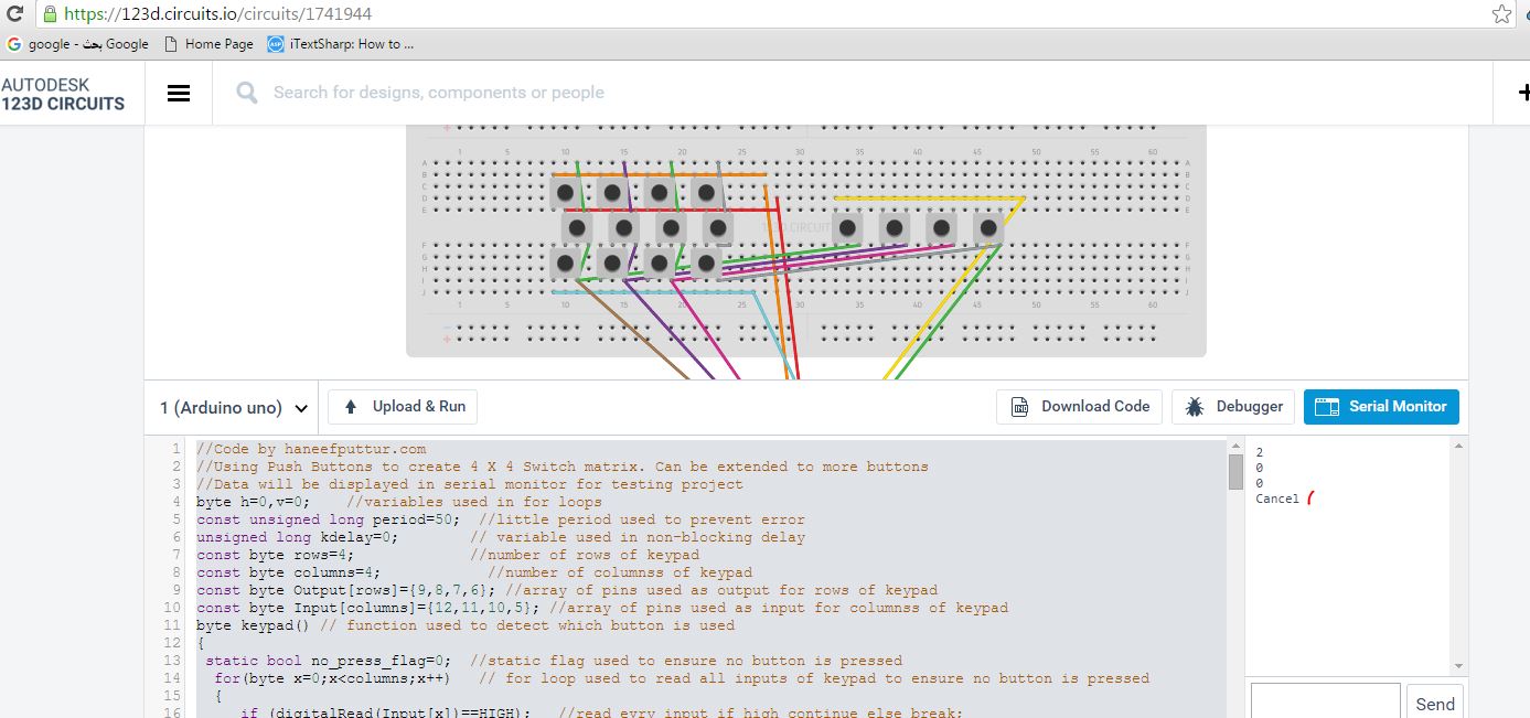
Breadboard Connection
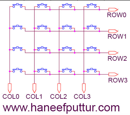
Schematic
PCB
Sketch / Code
//Code by haneefputtur.com
//Using Push Buttons to create 4 X 4 Switch matrix. Can be extended to more buttons
//Data will be displayed in serial monitor for testing project
byte h=0,v=0;    //variables used in for loops
const unsigned long period=50;  //little period used to prevent error
unsigned long kdelay=0;        // variable used in non-blocking delay
const byte rows=4;             //number of rows of keypad
const byte columns=4;            //number of columnss of keypad
const byte Output[rows]={9,8,7,6}; //array of pins used as output for rows of keypad
const byte Input[columns]={12,11,10,5}; //array of pins used as input for columnss of keypad
byte keypad() // function used to detect which button is used
{
 static bool no_press_flag=0;  //static flag used to ensure no button is pressed
  for(byte x=0;x<columns;x++)   // for loop used to read all inputs of keypad to ensure no button is pressed
  {
     if (digitalRead(Input[x])==HIGH);   //read evry input if high continue else break;
     else
     break;
     if(x==(columns-1))   //if no button is pressed
     {
      no_press_flag=1;
      h=0;
      v=0;
     }
  }
  if(no_press_flag==1) //if no button is pressed
  {
    for(byte r=0;r<rows;r++) //for loop used to make all output as low
    digitalWrite(Output[r],LOW);
    for(h=0;h<columns;h++)  // for loop to check if one of inputs is low
    {
      if(digitalRead(Input[h])==HIGH) //if specific input is remain high (no press on it) continue
      continue;
      else    //if one of inputs is low
      {
          for (v=0;v<rows;v++)   //for loop used to specify the number of row
          {
          digitalWrite(Output[v],HIGH);   //make specified output as HIGH
          if(digitalRead(Input[h])==HIGH)  //if the input that selected from first sor loop is change to high
          {
            no_press_flag=0;                //reset the no press flag;
            for(byte w=0;w<rows;w++) // make all outputs as low
            digitalWrite(Output[w],LOW);
            return v*4+h;  //return number of button
          }
          }
      }
    }
  }
 return 50;
}
void setup()
{
  for(byte i=0;i<rows;i++)  //for loop used to make pin mode of outputs as output
  {
  pinMode(Output[i],OUTPUT);
  }
  for(byte s=0;s<columns;s++) //for loop used to makk pin mode of inputs as inputpullup { pinMode(Input[s],INPUT_PULLUP); } Serial.begin(9600); //to use serial monitor we set the buad rate } void loop() { if(millis()-kdelay>period) //used to make non-blocking delay
  {
    kdelay=millis();  //capture time from millis function
switch (keypad())  //switch used to specify which button
   {
            case 0:
            Serial.println(1);
       break;
            case 1:
            Serial.println(2);
       break;
            case 2:
            Serial.println(3);
       break;
            case 3:
            Serial.println("F1");
       break;
            case 4:
            Serial.println(4);
       break;
            case 5:
            Serial.println(5);
       break;
            case 6:
            Serial.println(6);
       break;
            case 7:
            Serial.println("F2");
       break;
            case 8:
            Serial.println(7);
       break;
            case 9:
            Serial.println(8);
       break;
            case 10:
            Serial.println(9);
       break;
            case 11:
            Serial.println("F3");
       break;
            case 12:
            Serial.println("Mode");
       break;
            case 13:
            Serial.println(0);
       break;
            case 14:
            Serial.println("Cancel");
       break;
            case 15:
            Serial.println("Enter");
       break;
            default:
            ;
}
}
}
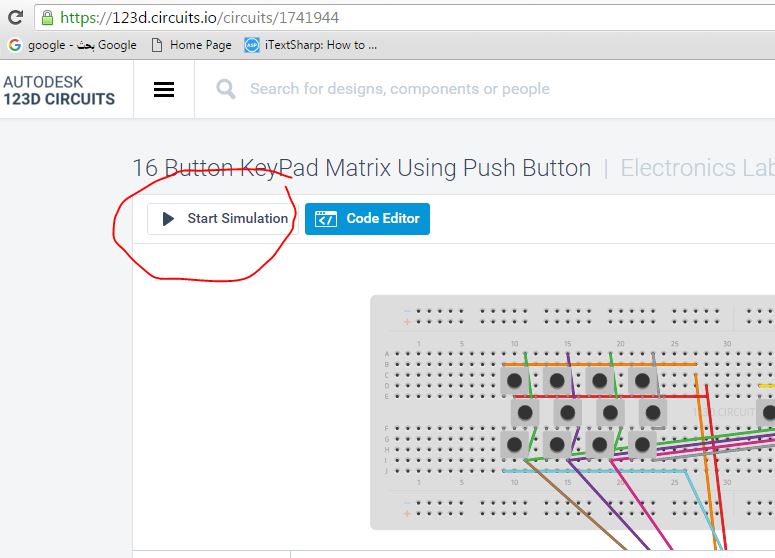
To see the simulation visit my lab at : https://123d.circuits.io/circuits/1741944
and click start Simulation.
You can press buttons and see the outputs at Serial Monitor